|
Autometer 2 5/8" Transmission Temperature Gauge.
This a brief summary of the gauge install and takes a short amount of time to do so.
|
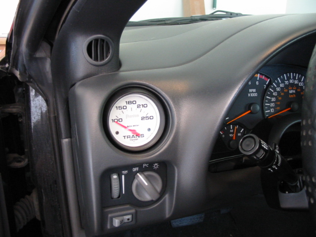 This is what it will look like when the gauge is installed.
Looks great doesn't it:)
This is what it will look like when the gauge is installed.
Looks great doesn't it:) |
 Installing the gauge into the vent.
Once you empty the gauge kit, you will notice the gauge has a cardboard ring around it. Leave it on there because this will aid on the mounting of the gauge. Also, the kit includes a green and red boot, to choose from, for nigthtime illumination. Remove the light from the rear of the gauge and install the boot of choice. You can also not install one and have white illumination. Now, remove the AC Vent. This can be a pain, but there are two snap rings behind the slats. Squeeze them and the AC vent should come out. Better said than done:( On the back of the gauge, you will see 5 connections. You will need to cut 5 pieces of wire for each connection and I used 18 gauge wire. I cut the following wires to these lengths:
Installing the gauge into the vent.
Once you empty the gauge kit, you will notice the gauge has a cardboard ring around it. Leave it on there because this will aid on the mounting of the gauge. Also, the kit includes a green and red boot, to choose from, for nigthtime illumination. Remove the light from the rear of the gauge and install the boot of choice. You can also not install one and have white illumination. Now, remove the AC Vent. This can be a pain, but there are two snap rings behind the slats. Squeeze them and the AC vent should come out. Better said than done:( On the back of the gauge, you will see 5 connections. You will need to cut 5 pieces of wire for each connection and I used 18 gauge wire. I cut the following wires to these lengths:
+12Vdc - 2 feet
+12Vdc Ground - 3 feet
Temp Signal - 5 feet
Temp Signal Ground - 3 feet
+12Vdc Illumination - 2 feet
Install ring crimp connectors on to each wire and install them on the back of the gauge using the supplied hardware. I also wrapped them with 3M electrical tape for added protection against electrical shorts. Be sure to mark the wires on both ends.
Now, pull out the dash trim bezel and it is held in with friction snaps. This the rounded bezel over the dash cluster. Look into the AC Vent and you will see foam separating the bezel and the dash. Route the wires down through the foam. Remove the rectagular panel under the steering wheel and it is held in with 4 screws. Two on the front of the panel and two just under the dash. Be careful of the trunk release button since the wires are small. Remove the trunk release button from the panel.
Now, pull the wires down from where they were inserted from the AC Vent. Take the two grounds, tie them togther and install a ring crimp connector. Find a metal frame, for grounding purposes, to install the ring and secure.
|
 Mounting of the Gauge.
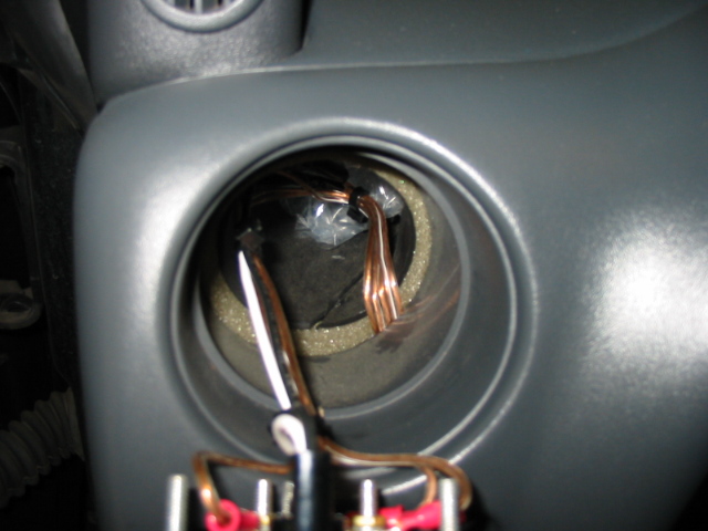
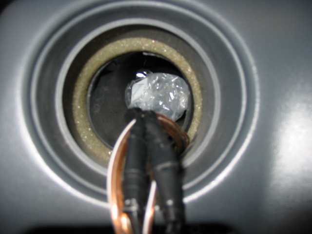
Prior to mounting of the gauge, insert some bubble wrap or something similar into the vent tube. This will keep cold air from directly hitting the gauge. Now, position the gauge into the AC vent and press it in. The friction will keep the gauge in place.
Mounting of the Gauge.
Prior to mounting of the gauge, insert some bubble wrap or something similar into the vent tube. This will keep cold air from directly hitting the gauge. Now, position the gauge into the AC vent and press it in. The friction will keep the gauge in place. |
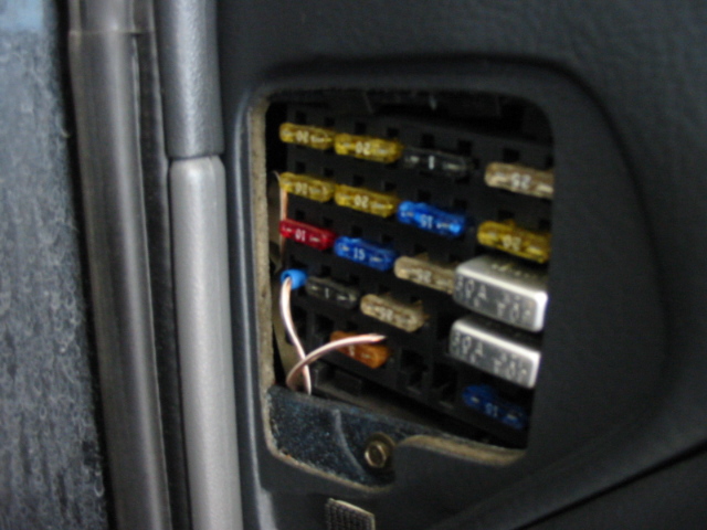 This is the power connections for the gauge.
Take the +12Vdc wire and it will be installed into the unused IGN port in the fuse box. This is a switchable 12Vdc source and the gauge will have no power when the key is turned off. Cut the desired length and intall a blade crimp connector. Install the wire. The illumination connection just uses the dimmer fuse. This way, you have dimming control over the gauge at night. All I did was cut the wire to desired length and stripped back some insulation. Twist the wire strands and stick the wire into the right side of the fuse. Meaning the wire and fuse share the same jack in the fusebox.
This is the power connections for the gauge.
Take the +12Vdc wire and it will be installed into the unused IGN port in the fuse box. This is a switchable 12Vdc source and the gauge will have no power when the key is turned off. Cut the desired length and intall a blade crimp connector. Install the wire. The illumination connection just uses the dimmer fuse. This way, you have dimming control over the gauge at night. All I did was cut the wire to desired length and stripped back some insulation. Twist the wire strands and stick the wire into the right side of the fuse. Meaning the wire and fuse share the same jack in the fusebox. |
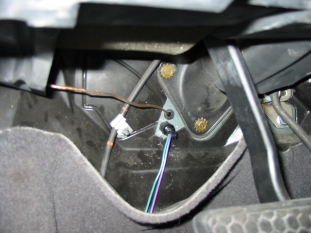 Passing the wire through the firewall.
Cut away a small piece of plastic covering the firewall. Drill a small pilot hole in the firewall to pass the wire through. The kit domes with a grommet to be installed in cases like this. Then, drill the hole to proper size and install the grommet. This will protect the wire from the sharp edges of the firewall preventing electrical shorts or damage to the gauge.
Passing the wire through the firewall.
Cut away a small piece of plastic covering the firewall. Drill a small pilot hole in the firewall to pass the wire through. The kit domes with a grommet to be installed in cases like this. Then, drill the hole to proper size and install the grommet. This will protect the wire from the sharp edges of the firewall preventing electrical shorts or damage to the gauge. |
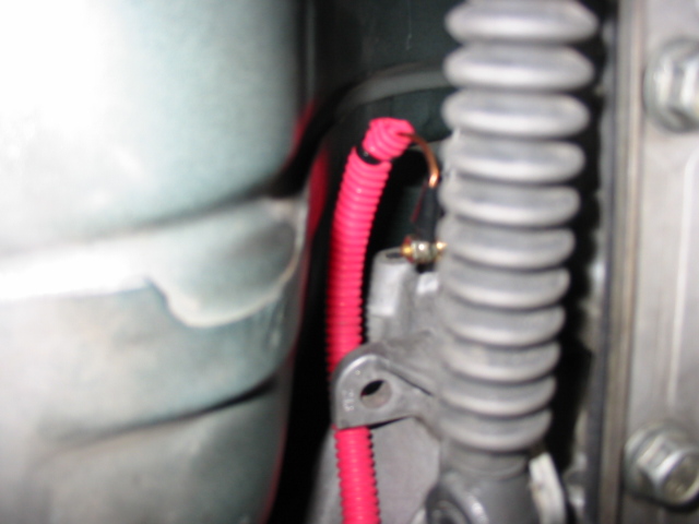 The connection the transmission.
On the Automatic Transmission euipped F-Body, there is a perfect connection to mount the Autometer sending unit. This is applicable for the 4L60E, 4L60 and 700R4 Transmissions. On the driver's side of the transmission about half way up, you will see a bolt sticking out. Remove the bolt and no transmission fluid will come out. Now, wrap the threads of the sending unit with some teflon tape. The sending unit will thread into the hole in the side of the transmission. What a perfect fit:)
The connection the transmission.
On the Automatic Transmission euipped F-Body, there is a perfect connection to mount the Autometer sending unit. This is applicable for the 4L60E, 4L60 and 700R4 Transmissions. On the driver's side of the transmission about half way up, you will see a bolt sticking out. Remove the bolt and no transmission fluid will come out. Now, wrap the threads of the sending unit with some teflon tape. The sending unit will thread into the hole in the side of the transmission. What a perfect fit:)
Now, route the wire down to the sending unit. I also installed some flex loom to protect the wire. Also, tie wrap the wire out of the way from hot exhaust parts. Once, you have this completed, cut the wire to length. Install a ring crimp connector and install it on to the sending unit. The nut, I believe, is 7mm.
|
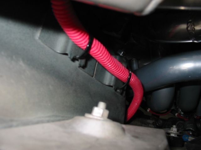 A couple of good tie wrap points.
Tie wrapped the wire free from the hot exhaust parts like the Hooker LT Headers.
A couple of good tie wrap points.
Tie wrapped the wire free from the hot exhaust parts like the Hooker LT Headers. |
|